| PanoramIX Mini Pan Head | |
| Pan Head Calibration | |
| PanoramIX Links | |
Pan Head Calibration
|
BackgroundMost standard lenses can be approximated by a virtual pin-hole or "nodal point". This is equivalent to reducing the aperture to almost zero, or infinite f-stop. All rays of light striking the film appear to pass through this point. This is illustrated in the following diagram.  The black box represents the simplified camera. The orange line on the bottom represents the film being exposed. The gap at the top represents the pin hole (nodal point of the lens). The blue circle represents some object in view of the camera. Light reflected from the blue object follows the gray line through the pin-hole and strikes the film on the left side where an image of the object is recorded on the film. The view direction of the camera can be represented by an arrow which is perpendicular to the film and passes through the pinhole, as shown in the following diagram:  The view direction is represented by a red arrow. In this case, the camera is aimed to the left of the blue object. Light reflected from the blue object follows the gray line, passes through the pinhole, and strikes the film to the left of the center. The vertical bar on the right side represents the background beyond the blue object. Following the gray line back beyond the blue object leads to the point on the background which is hidden by the blue object. The following image presents an example of these conditions. In this case, the blue object in the diagram is represented by the back of a chair placed close to the camera. The background contains a fireplace and surrounding walls. Part of the chair lies in front of the third tile over the fireplace, and a smal part of the fourth tile. 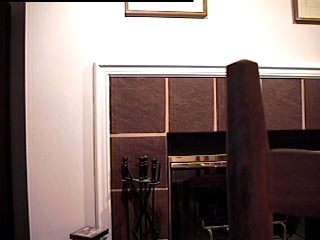 The following diagram shows what happens when the camera is rotated by a point behind the pin-hole.  In this case, the camera has been rotated to the right until the view direction points to the right of the blue object. The axis of rotation is located at the base of the direction arrow. Light reflected from the blue object follows the green line through the pin-hole and strikes the film to the right of the center of the film. In this case, the green line is not the same as the gray line representing the path of the light from the object to the camera for the previous shot. As a result, for this shot, the camera sees the blue object from a different direction compared to the previous shot. In addition, following the green line back to the background shows that the part of the background hidden by the blue object in this shot is located to the left of the part of the background hidden by the same object in the previous shot. The following image shows what happens in a real scene. 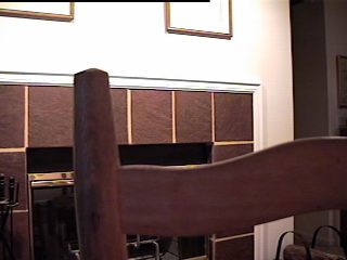 In this case, the camera used to capture the previous image was rotated to the right until the back of the chair was seen to move from the right side of the image to the left side of the image. As a result of the rotation of the camera, the entire scene has been shifted to the left within this image, as expected. The back of the chair, however, has moved to the left even more than the background. Now the back of the chair covers parts of the second and third tiles over the fireplace. The grout between the third and fourth tiles is now completely exposed, and the grout between the second and third tiles is completely hidden. This shifting of the chair relative to the background is called a parallax effect. Because of this parallax effect, this pair of images is not suitable for merging together into a panoramic image. It is not possible to align both the foreground (the chair) and the background (the fireplace) to form a single image. The parallax effect can be eliminated by rotating the camera about the virtual pin-hole. This is illustrated in the following diagram:  In this case, the camera has been rotated by the same amount as in the previous diagram. This time, however, instead of rotating the camera about the base of the direction arrow, the camera has been rotated about the virtual pin-hole. As in the original shot, light reflected from the blue object follows the gray line, passing though the pin-hole, and striking the film. Since this is exactly the same path followed in the first shot, following this line back to the background shows that the part of the background hidden in this shot is exactly the same as the part hidden in the original shot. The following image shows the result of rotating the camera about the virtual pin hole instead of a point behind the pinhole: 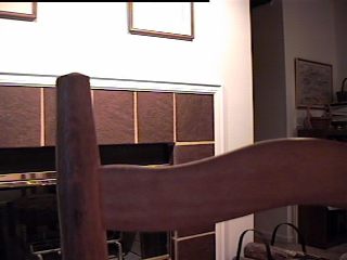 In this case, the image of the chair has shifted to the left by exactly the same amount as the background, no more and no less. The portion of the background hidden by the chair in this image is the same as is hidden in the orginal shot. Having eliminated the parallax effect, this image is consistent of coherent with the first image. These tow images may now be merged into a single image representing part of a panoramic image. The following image shows the result of merging the previous image with the original image. 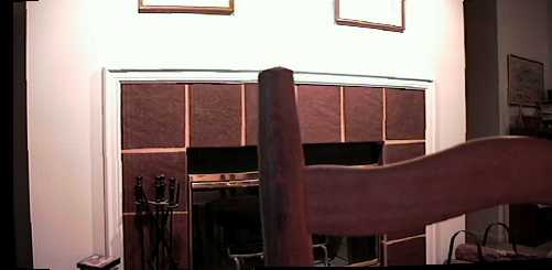 Calibrating the Mini Pan HeadThe process of calibrating the PanoramIX Mini Pan Head consists of adjusting the position and orientation of a camera on the Mini Pan Head so as to minimize or eliminate the parallax effect. If you have an SLR camera, or a digital film camera, you can use the following procedure:
In order to calibrate the Mini Pan Head accurately, it helps to exaggerate the parallax effect as much as possible. To do this, place the test object as close to the camera as possible as long as the camera can still focus on both the test object and the background. Ideally, the distance from the camera to the test object will be much less than the distance from the camera to the nearest visible object in real scene to be captured for a panoramic image. The calibration needs to be performed only once for a particular camera. Do this once in your home, office, studio, or other convenient place and mark the result on the Mini Pan Head. Then go and shoot panramic scenes using the same calibration settings established beforehand. If you have a non-SLR camera, like most "point-and-shoot" models, then you cannot tell where the camera is being aimed. The non-SLR viewfinder (rangefinder) has a large parallax error of its own, so it is useless for calibration. In this case, you may need to shoot a test roll of film, carefully noting how the camera was adjusted for each shot. Instead of shooting a test roll of film, you may perform a crude calibration of the Mini Pan Head by following the first four steps listed above. In this case, although the parallax effect may not be eliminated completely, it will be much less than would be encountered if the camera were mounted directly on the tripod without the Mini Pan Head. All diagrams shown in this page were drawn by William Luken. All images shown on this page where created by William Luken. All items seen in these images are the personal property of William Luken. Last modified Sept. 20, 1998. Last updated January 11, 1999; October 11, 2001; January 27, 2006; June 5, 2013 |